Publication categories
Publications - Engineering aspects
Design and operation experience of laser emission detection device
For the lidar signal detection in a radar warning receiver (RWR) very simple design solutions like a single-limit comparator after the input amplifier are often used. Further processing is conducted with the help of the built-in processor, which uses only the values of time intervals between pulses for the analysis. It is clear that such an approach to the detection problem solving has multiple disadvantages. For example, the comparator output signal has passed a non-linear and irreversible transformation and the pulse amplitude information is lost irreversibly. Besides, it is rather common to use a comparator static threshold, which is set with a "reserve" so that a sudden increase of the external noise level (sun glare, etc.) does not put the system out of the operating mode. Of course, this solution leads to a serious decrease of the RWR sensitivity.
As a result, the civil lidar detection system (as part of car radar detectors) can operate only when the beam hits directly the receiver. It is given by lidar detectors ad makers as a fact, which occurs due to the laser speed measuring principle. Police lidars ad makers rightly assign the generally accepted RWR disadvantage to the advantages of their measurement method and feel no sadness about it at all. Some automobilists, usually those who consider themselves as much more cleverer, install active lidar suppressors, and in most cases they run continuously from the switch starting till the end of the trip.
Let us try to consider the possibility of signal detection and recognition of the police lidar by the reflected and /or scattered beam. Let us assume that the scattering is provided by the atmosphere, which always contains a certain amount of fine dust on a highway. One should also keep in mind the non-zero probability of the beam reflection from the body of the roadway (while measuring the speed of the car ahead) or multireflection from the car surface and local items.
Firstly, let us consider the stress-strain diagram in the standard scheme in case of the receiving photodiode hitting the lidar beam.
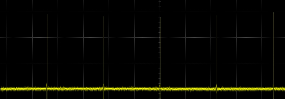
Fig.1. Preamplifier output signal oscillogrope display. One can see the short pulses, the level of which is much higher than the noise level.
It is obvious that the additive mixture of internal and external noise with the useful signal, which is a short (20 ... 50 ns) pulse, will be recorded at the amplifier output. This pulse, having passed the comparator, "regenerates" to the standard digital signal with the same duration.
In case of receiving of the pulse, scattered by fine dust, the diagrams at the amplifier output will be completely different.
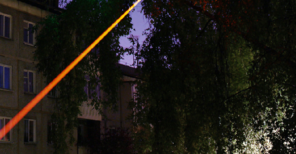
Fig.2 Snapshot of the laser beam in the atmosphere. In this case the beam passes through the field of camera view, but it does not fall into it.
It is necessary to keep in mind in case of the lidar operation, which by the definition has a pulsing nature of radiation, that the laser pulse duration (20...50 ns) defines only the luminous segment length in the field of the detector view, i.e. 60...150 sm. 60…150 сm.
Actually, a glowing cylinder is flowing in the detector field of view with the light speed (of course, only if the beam does not hit the lens). The glow time is determined not by its length, but by the length of the beam in the field of view and, which in our case is equal to hundreds of nanoseconds.

Fig.3. Shooting of short laser pulse by a high-speed camera (http://www.nature.com/ncomms/2015/150127/ncomms7021/full/ncomms7021.html)
As a result, it is the time of glowing object existence within the RWR field of view that defines the length of the electrical input pulse. It comes natural for the case when the laser beam crosses the field of view normally to the optical axis of the receiver. At all other angles the input pulse duration increase will be different.
Let us assume that the lidar beam is directed towards the receiver and it is in the field of view of the detector.
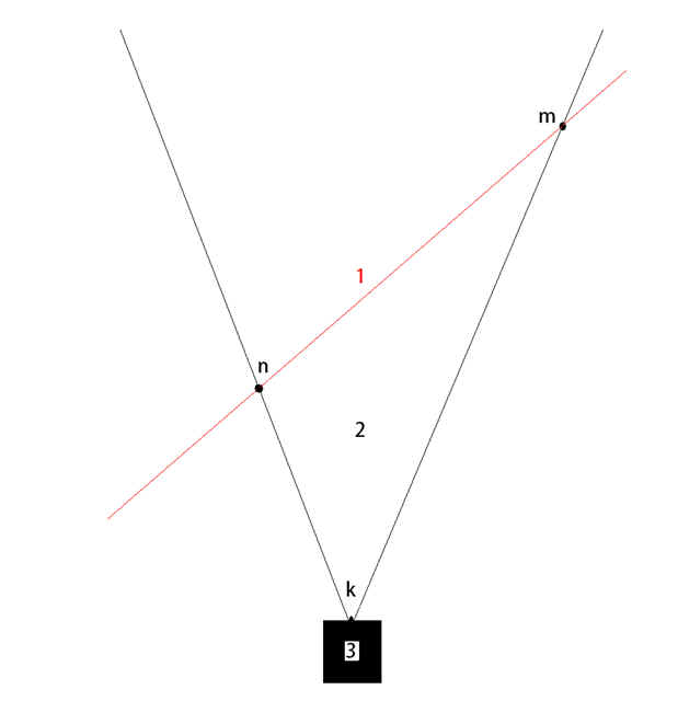
Fig.4. Lidar beam (1) is crossing the field of view (2) of lidar detector (3).
Then the value of the pulse stretching of the passing beam in seconds will be T=(mn+nk-km)/C, where the length of the interval is defined in meters, and the speed of light - in meters per second. In the case of the beam coming after, T = (mn + km-nk) /C, i.e. much more. For practical working conditions of the police lidar, the pulse stretching will come up to tens or hundreds of nanoseconds for passing beams and up to microseconds for the beams, which are coming after. It should be borne in mind that the signals will not have short front edges, because the pulse form will be determined by the multiplier of the input light flux and the directivity diagram of the optical system.
So, one will record at the amplifier output not a 20...50 ns pulse, but a stretched irregular fragment of a self-noise lifting above the zero line with flattened falloff, and a smoothed front in most cases. If the amplifier has a meaningful constraint of the "bottom" bandwidth or any elements of the matched filtering, designed for the pulse lidar duration (20 ... 50 ns), then the extended in time signal will be suppressed, and its detection will become virtually impossible.

Fig.5. Short (1) received pulse (beam hits the lens) and "stretched" (2) pulse (beam passes through the field of view, but misses the lens).
The situation is aggravated by the fact that in some detectors an input pulse differentiation is used with the following processing by a dual-limit comparator. This circuit solution actually improves the efficiency of a short pulse detection (assuming the input noise is normally distributed and having the input signal with a small excess above the "sigma" it is possible to succeed in getting a smaller amount of target missing. However, in case when a signal is formed by the scattered beam, this method will prevent further detection: an integrator is needed for the accumulation and "dual threshold" circuit differentiator just interferes with detection.
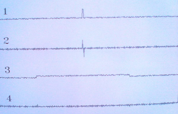
Fig.6. Short high-amplitude pulse (1) passes through the differentiator and is appropriate for a dual-limit comparator selection (2). Long low amplitude pulse (3), passing through the differentiator, gives almost no response (4). Detection after the differentiator is impossible, although the long pulse energy is much bigger in this case.
So, in order to detect short and long pulses, the designed input amplifiers should meet the following requirements: have an extended "down" passband (up to the time of the 1 microsecond order), and also have an integrating circuit with a time of 0.1 ... 0.3 ms. Besides, for the sensitivity increase during the work with short pulses of low amplitude, it is necessary to implement the principle of a dual-limit comparator. As the classic differentiator cannot be applied in this case, it is necessary to use other circuit solutions.
To test the designed amplifier let us inject ultra-low power input optical signals with a pulse duration of 50 ns and 1000 ns.
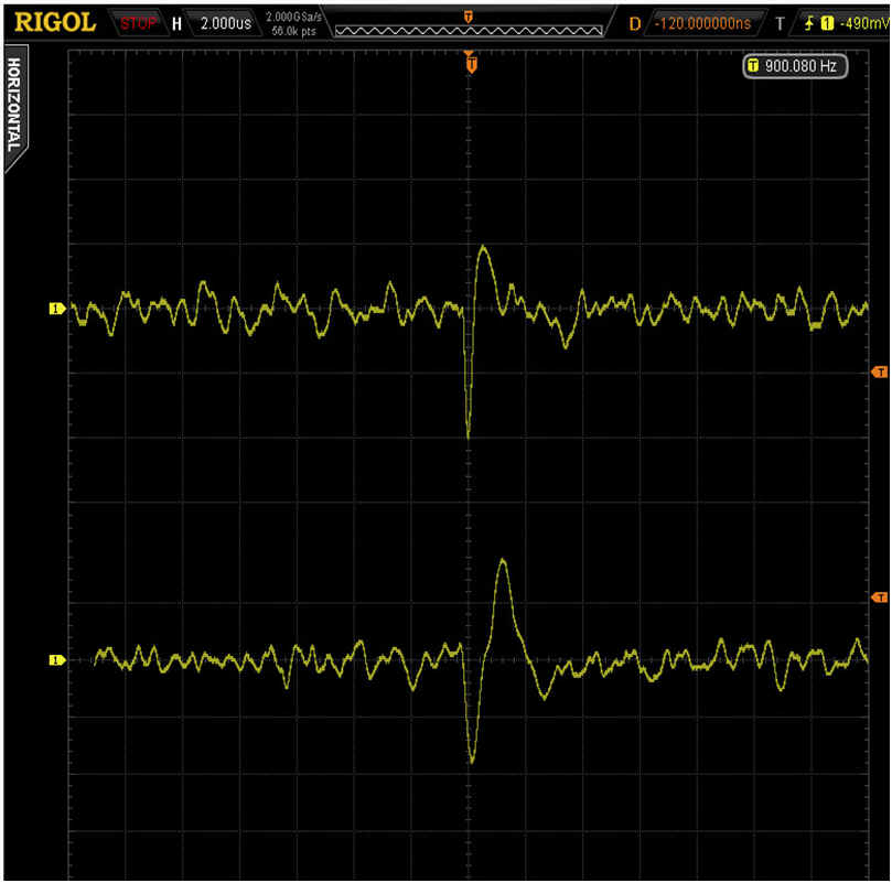
Fig.7. Oscillogrope display of the preamplifier response to a low-level input pulse of 50ns (top) and pulse of 1000ns (bottom). Signal-to-noise ratio is 3:1. The requirement of the work with different duration pulses is fulfilled (NB! signals are inverted).
Further processing includes two multidirectional peak detectors, which are connected to the inputs of the instrumentation operational amplifier. Thus, the information about the pulse amplitude is saved, that allows us to apply adaptive and tracking thresholds, which are in compliance with Bayesian criteria. At the same time all the advantages of the dual-limit comparator solution also preserved, as the Op Amp output signal has no longer normal, but the Rayleigh distribution (because the signal has become unipolar).
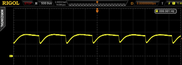
Fig.8. Inverted output signal of the operational amplifier. Pulses follow at a 900 Hz frequency.
It makes sense to run the following signal analysis in the digital version. Several conflicting requirements appear here. Ideally - a threshold, after its overcoming the pulse detection decision is made, should provide equal first and second type error rates. However, during the real device application, the input noise level is constantly and unavoidably "floating", and that requires the dynamic threshold use. At the same time, the threshold adaptation rate cannot be constant, because the sudden sunlight exposure of the device requires quick adaptation, and the monitoring of the series of low-level pulses requires slow one.
The best solution for the dynamic threshold turned to be the counting of the number of intersections within a fixed time. It is easy to keep the observation with a given coefficient of sigmatic deviations, and the intersection confirmation comes only after exceeding the value of 4.5 "sigma" (here, by the way, the advantage of the stored information about the pulse amplitude is realized). However, in the case of a rapid noise level increase such system does not always manage to adapt.
It makes sense to use the tracking threshold to avoid similar collisions, which can never be lower than the dynamic one. It is calculated as a half of the half-sum of the previous threshold value and the peak value of the previous pulse.

Fig.9. Amplitude varying signal. The tracking threshold level is marked with blue color (using 0.8 coefficient instead of 0.5 for clarity)

Fig.10. The case of pulse skipping while using non-Bayesian threshold value. However, after a certain time limit the threshold begins to decline. This time is chosen at the rate of maximum time distance between the pulses of the police lidar with the lowest frequency.
So, while using the tracking and dynamic thresholds, it is possible to get the transformation of the input signal into a sequence of numbers, describing the temporal distance between the fixed pulses. Further processing principle is obvious: it is necessary to compare constantly the obtained numerical array with the signature of known lidars. Besides, it makes sense to use along a heuristic algorithm, based on a priori known autocorrelation characteristics of lidar signals.
The optical system does not have any distinctive features. Usually the Kepler scheme or a single lens (taking into account the curvature of spherical surface of the receiving photodiode. The viewing angle is 20˚, but if the field of view is estimated as the directional diagram, than the half-power level will be equal to 12˚. The sensitivity was more than satisfactory even when working through the windshield of the car.
The first experimental device along with standard detectors «Conqueror» and «Crunch» (which were fixed on the top and bottom of the windshield) was tested for a year and a half. The device was placed next to the driver headrest, i.e. the windshield provided the same signal attenuation.
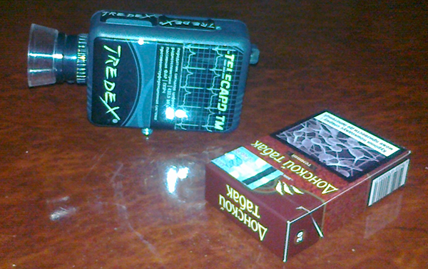
Fig.11. The exterior design of the first experimental device.
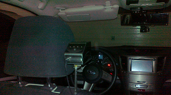
Fig.12. The second detector model, the mounting place. It becomes possible to get many interesting and unexpected results with its help.
The test methodology was as close to the real operating conditions as possible: there is the post of traffic police at the city entrance, which is not lazy to measure all "fast-going-goals" speed with the help of «TruCam» lidar. As the author has to pass this post twice during the working day, it was easy to wait for the next candidate for the fine and move behind him at a 100-200 meters distance. Moments of the lidar pulse detection were recorded from both the experimental device and the standard detectors «Conqueror» and «Crunch», and the digitized signal from the Op Amp output was recorded for further analysis and signature clarification. Of course, these signals were recorded even in the case of the author's car speed measurement.
The standard detectors (both!) have never came into action during the speed measurement of the car moving ahead during all observation. In case of the lidar work directly on my car the detections were about three times out of ten. Thereat, there was no single chance to detect the lidar work from a distance of more than 300 meters. There were no false activation during the tests. In principle, these are expected results, they are almost identical to those published by other users (perhaps, "elite" models work better, but such data could not be found).
The experimental device gave completely different results. The fact of the lidar work on the car moving ahead was considered to be valid, if the traffic police officers stopped it, or the aiming was detected. In all these cases, the radiation was detected, no missing noticed. In addition, while approaching the place of measuring multiple lidar radiation was recorded, the maximum distance was about 600 meters. The lidar work on the author's car was always detected. There were no false alarms because of natural causes (changing light conditions, directing the lens in the direction of the sun, the work of LED traffic lights, xenon headlights of oncoming cars, etc.).
Here our reader has the right to call the author accountable and demand an explanation: how is that possible - RWRs of the respected companies keep silent, and the toy made by the unknown office from the third world country steadily detects and recognizes signals? Does not it resemble the advertising texts of pharmaceutical companies, where an immediate healing, eternal youth and returning of full head of hair are promised in case if a naive patient sends them some money for the obvious placebo?
The answer is known since the 70s of the previous century. So, "... This kind of device sensitivity increase allows to detect not only the direct laser radiation, i.e. within the laser beam spot on the object, but also the laser radiation scattered in the atmosphere, because the intensity of the scattered forward laser radiation within an angle of 1°…2° is about 2 orders less than in the direct beam" [1],[2]. It turns out that the lidar detector must work in all cases, when the laser beam is aimed at the car, in which it is located, and not only when the beam hit straight the lens. And if it is not so, then the detector (despite its respectable "label" on the lid) is just stupid, goofy and good for nothing. Moreover, it was obliged to "see" the lidar beam even in the case of more considerable deviations than 1°…2°, it is so because the aerosol scattering over highways is much more higher than the molecular: "... wind-borne dust and salt particles, products of combustion (soot, ash), condensed organic residues and substances formed during chemical reactions are classified as aerosols in the atmosphere...». [3]
The following illustrations can confirm the above mentioned:
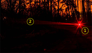
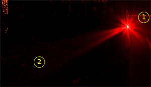
Fig.13. Illustration of distinctive features of laser radiation formation and distribution of red semiconductor laser in the atmosphere. (Author of the photo - Elena Pavlovich).
1. Laser emitter.
2. The path of the laser radiation (laser beam).
Thus, the "hydrometeors, fine dust and other smallest particles, which are permanently present in the atmosphere, rereflect the laser radiation falling on them in a wide spatial angle, so that the laser beam is visible not only when viewed at a zero angle to the axis of the laser radiation, but at larger angles to it". In simple terms, the propagation path of the laser radiation is "shining" in the relevant frequency range.
From the illustrations it comes clear that the lidar is the source of a poweful radiation flow not only in the propagation axis direction, but in other directions, at a big enough angels to the optical axis. This means that if the police lidar is in the field of view of the detector, the presence of a modulated laser radiation has to be recorded by standard working radiation warning system, even if the laser beam did not hit the receiver lens.
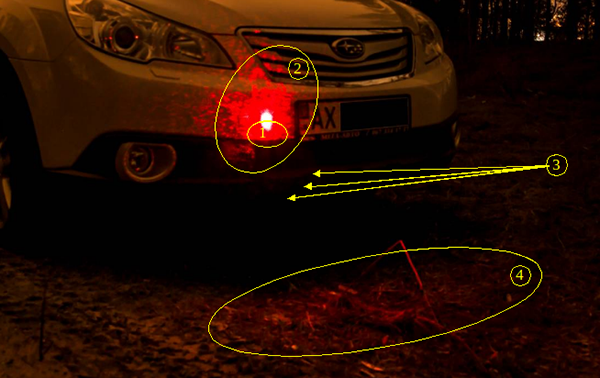
Fig.14. Reflection of the laser radiation from the car body elements (Author of the photo - Elena Pavlovich).
1. The point of the laser beam hitting the front bumper.
2. The diffuse reflection of the laser radiation from the car front projection parts.
3. The reflected radiation caught by the camera.
4. The part of the roadside lit in red color (in this case) in front of the car bumper - is a result of the laser radiation reflection from the diffuse reflective surface.
Thus, the idea that the whole energy flow is emitted only inside the lidar formed laser beam while the laser emitter is turned on is quite a rough approximation to the reality. In fact, not only the whole beam path and the emitter itself is radiant, but also, due to the multiple rereflection, the atmosphere above the road body, the car, which is hit by the laser beam, and all other objects on the road and near to it, which get scattered laser radiation. The work of the laser emitter under the atmosphere conditions is certainly induce the shining along the beam propagation path, including the lidar. Of course, the power of this rereflected radiation is far below than the power of the direct radiation, this imposes high requirements to radiation warning system sensitivity.
Practical verification of the different RWRs sensitivity vs the scattered laser radiation revealed unexpected effects, which explain the limited operation of lidar detectors that are produced by many companies.
https://www.youtube.com/watch?v=Ek-J2eMkCvY
Some of the results are not very clear even for the authors of the work, but "what you see is what you see".
A total surprise during the tests was the signals coming from some oncoming cars, mostly of luxury brands. It turns out that the laser jammers are very popular in Ukraine, and their power was amazing. In some cases it was possible to record the operation of such devices from a distance of 500 meters or more. Moreover, the detector was installed in the cabin, behind the windshield, and the directivity diagram of jammers was broad, unlike the lidars. And what is the power of these devices? It turned out that the jammers generate a periodic signal, which, however, differs from the «TruCam» signal, it made it possible to share the aims.
Here, perhaps, one can put a full stop. And if Beckenbauer said that "...football is the most essential of the non-essential things", the question of timely detection of the police lidars is certainly related to the non-essential area. Especially since the traffic speed control has been completely stopped (Sic!), but it is OK, we are getting along little by little. And jammer detection... Well, it is surely none of our business. But we hope that some of the scattered radiation receiving methods, which are used in the device, have the right to exist.
P.S. Into the device design also were involved: Igor Gaftonyuk (DSP, CPU programming), Vladislav Mishkin, Vadim Simanenko (analog part and optics), Roman Kirichenko (layout and housing).
________________________________________________________________________________________________
P.P.S.
The main business of TREDEX Company LLC is development and production of computer medical equipment. We aren’t going to develop a full-featured radar detector, because of microwave equipment is not included in our plans. However, we have reason to believe that we have developed the laser detector more effective than all samples of radar detectors that we have been able to test.
TREDEX Company LLC is interested in contacts with manufacturers of radar detectors with a view to commercialization of this product.
________________________________________________________________________________________________
[1] Zuev V.E. "The spread of the visible and infrared waves in the atmosphere", Ed. Soviet Radio, M, 1970.
[2] «Laser radiation detection device» http://poleznayamodel.ru/model/13/133325.html
[3] [PDF] Description of the process of optical distribution ... - Nag.ru
Category:
- Log in to post comments
PO box 11515, 61001 Kharkov Ukraine,
tel./fax: +38(050)0113940, +38(057)7290409
E-mail: tredex@tredex-company.com
tredex.office@gmail.com